
How should cantilever racking arms be configured for different load types?
Cantilever racking arms should be configured according to the load’s weight, length, rigidity and handling method. Set arm length and vertical spacing to support the load securely without excessive overhang, and select an arm capacity and frame arrangement suitable for the combined load at each storage level.
The correct cantilever arm configuration depends on how the load behaves when it is stored, not simply on its overall weight. Configuration should account for the load’s dimensions, centre of gravity, rigidity, contact points, bundle stability and method of placement. The resulting design should specify the arm type, arm length, vertical positions, rated capacity, frame arrangement and any retention or support accessories required.
Start with the load profile. Before selecting the arms, establish the maximum and typical load dimensions, individual and bundled weights, the number of storage levels and the way loads will be deposited or removed. A long, rigid steel section behaves differently from a flexible bundle of timber, while a concentrated coil load places different demands on the arms from evenly distributed sheet material. The design should reflect the least favourable realistic loading condition rather than an average load.
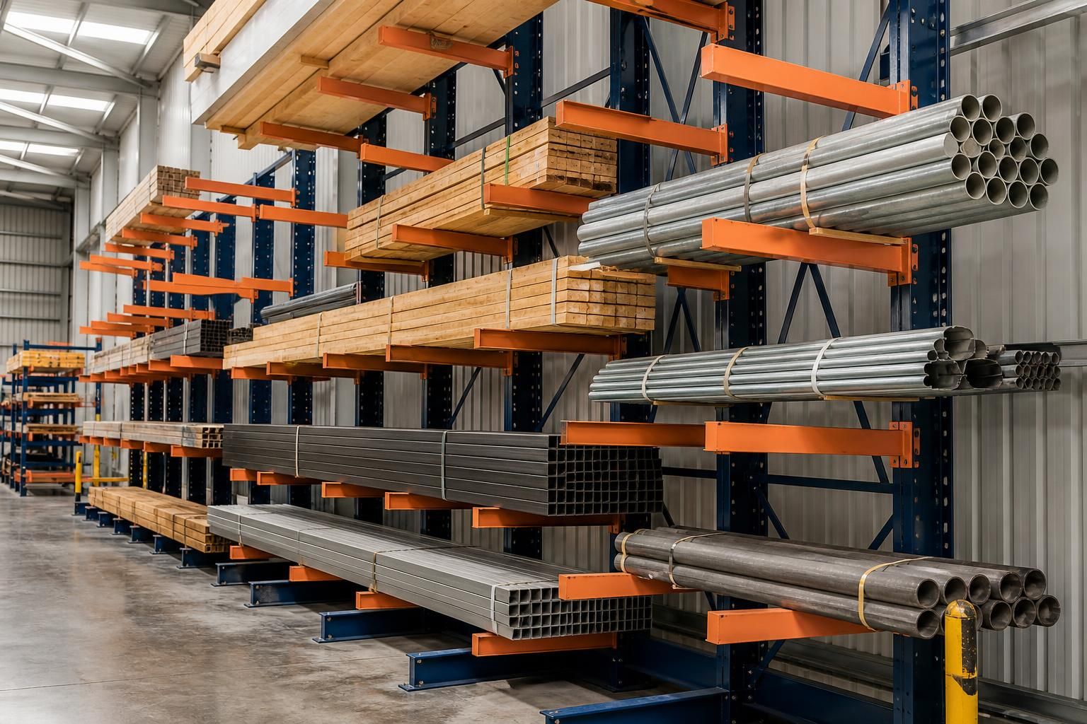
- Long, rigid sections: Use arm positions that provide sufficient support along the length while keeping the load stable during handling. If the section is prone to rolling or shifting, retention features or end stops may be needed, provided they do not obstruct safe loading and unloading.
- Pipes and round products: Round loads can roll towards the front or sideways unless the support arrangement controls their movement. Arm geometry, end stops, cradles or other suitable restraints should be considered, particularly where pipes are stored in bundles or at different diameters.
- Timber and sheet materials: These loads usually require broad, consistent support to prevent sagging, bending or local damage. Arms should be arranged so that the bundle remains supported across its bearing points, with the bundle secured against sliding where necessary.
- Flexible or bundled materials: Cables, plastics, fabric-based products and loosely bound items may deform between arms. Closer support positions, separators or containment may be more suitable than a basic open arm arrangement.
- Coils and concentrated loads: A coil can impose a high load over a limited contact area. The design must check both the arm’s local loading and the effect on the upright and base. Cradles or dedicated coil supports may be appropriate where they prevent rolling and distribute the load more effectively.
- Mixed stock: Where one rack stores several load types, configure each level for the most demanding intended use or divide the rack into clearly defined load zones. Do not assume that a capacity suitable for one product automatically applies to another with a different load distribution.
Arm length should match the load depth. An arm that is too short may leave the load inadequately supported, while excessive projection can increase bending forces and create unnecessary overhang. The usable arm length should therefore be based on the actual storage depth, required clearances and handling method. Loads should not project into aisles or interfere with adjacent bays, access routes or building features.
Vertical spacing should suit the product and equipment. Set the levels to accommodate the load height, the required clearance for forks or other handling equipment and the amount of space needed to place and remove the product without striking the arms above. Closely spaced levels may improve use of the available height for smaller items, whereas bulky or unstable loads require more room for controlled handling. The available building height, fire or service clearances and floor conditions should also be considered during the layout.
Capacity is determined by the complete arrangement. The stated capacity of an arm is not the only figure to check. The frame, base, connections, arm position, span between uprights and distribution of the load all affect the permissible working load. A load spread evenly across several arms creates a different demand from one concentrated at a single contact point. The design should use the applicable manufacturer’s load data and clearly identify the permitted capacity for each level or loading condition.
Where loads are placed by forklift, crane or another mechanical handling method, the configuration must also allow for the approach and withdrawal path. Forks or lifting attachments should not catch the arms, and operators should not need to push, drag or impact a load into position. If the handling method creates impact or sideways forces, these should be considered separately from the static load. The rack should never be treated as a convenient stop for moving equipment.
Use accessories only where they solve a defined risk. End stops can help retain round or unstable products, while dividers can separate different stock sizes and reduce sideways movement. Protective components may be required where handling equipment could contact the frame. Accessories must be compatible with the rack and must not reduce the clear loading space, create a trip or snag point, or encourage loads to be placed beyond the intended support area.
A practical configuration review should record the heaviest load, maximum load depth and length, bundle condition, contact points, loading sequence and handling equipment. It should then show the proposed arm positions, load zones, capacities and any restrictions on use. Clear identification is especially important for mixed-use racks, so that a level intended for lighter or more evenly distributed stock is not later used for a concentrated load.
For a bespoke installation, Spartan Direct’s consultation may include a site meeting and survey, followed by written proposals and working drawings. This allows the arm arrangement to be checked against the building, access routes, handling equipment and the products actually being stored, rather than relying on a standard rack layout. Where required, project management can continue through installation and final commissioning, with the completed arrangement handed over for use in accordance with its stated capacities and operating controls.
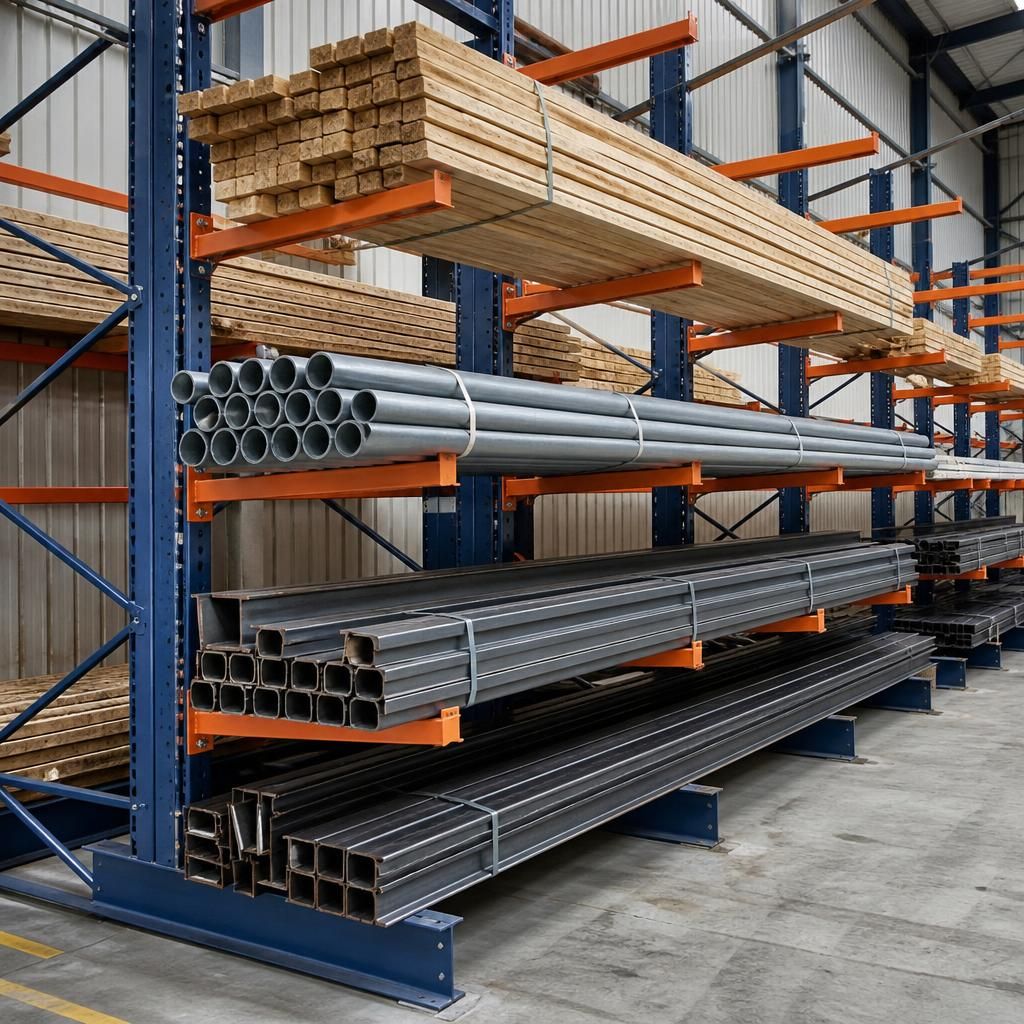
The load’s centre of gravity is as important as its weight when configuring cantilever arms. An uneven or asymmetrical item can place more force on one arm or one side of the rack, even when its total weight appears suitable. The support arrangement should therefore keep the load’s centre of gravity within the intended bearing area and prevent the item from tipping, rotating or sliding during storage.
This is particularly relevant for products with an uneven profile, a heavier end or an irregular underside. The proposed layout should show where the load is expected to make contact and whether additional supports, separators or restraints are needed. A load plan can then identify the permitted position and orientation for each product, helping operators avoid placing an item in a way that changes the forces on the arms.